
The element
that decides the budget.
Bridge deck slabs are the single highest-cost line in road maintenance budgets across Europe. The dominant failure mode is chloride-driven corrosion of the steel reinforcement under salt-water spray, de-icing salt, or both. GFRP, used as the top mat — and on full-GFRP decks — changes the budget profile for the next eighty years.
The hybrid section
does most of the work.
On a bridge deck, the chloride load almost always concentrates in the top fifty millimetres — the salt-spray and de-icing zone above the wearing surface. The bottom mat sits in a chemically benign environment and is rarely the first thing to fail. That asymmetry is what makes hybrid GFRP-on-top, steel-on-bottom sections so effective. GFRP eliminates the corrosion problem where it occurs. Steel retains a ductile load-path in the part of the section that never sees the salt.
Full-GFRP decks become economical for new builds in heavy de-icing-salt or coastal exposure. Lifecycle modelling shows steel reaching the end of its corrosion budget before the design service life is reached anywhere in the section.
The hybrid detail
in one diagram.
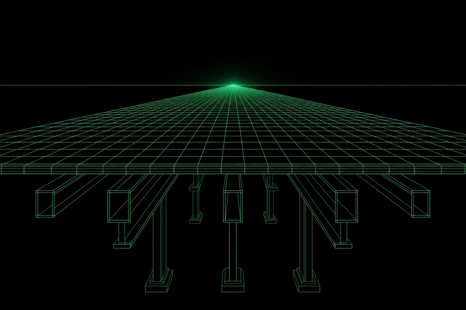
Six layers of a typical reinforced concrete bridge deck. The top reinforcement mat (the chloride-exposure zone) is GFRP; the bottom mat (the structural reserve) remains steel. The detail is well-established in international code practice.
Indicative section for a 250 mm reinforced-concrete deck on a road bridge with de-icing salt exposure. Project-specific detailing is part of every cooperation workshop.
Four ways deck
specifications come to us.
The four typical configurations we are asked to spec — covering new builds, refurbishments, and the parapet/deck interface that often defines the design.
- 01Hybrid section · new build
GFRP top mat (Ø 12 mm), steel bottom mat (Ø 16/20 mm). The most common detail for road bridges in chloride or de-icing-salt exposure. Lifecycle modelling typically extends design service life by 1.5–2× over a steel-only deck.
- 02Full-GFRP deck · new build
Both mats in GFRP. Specified for marine viaducts, coastal pier-deck combinations, and high-traffic Alpine motorway bridges. Lifecycle service life ≥ 80 years with no corrosion-driven major repair.
- 03Top-mat refurbishment · existing
Hydro-demolition of the existing top mat after corrosion-driven spalling. Replacement with GFRP welded mesh and repair mortar. Common refurbishment pattern in Switzerland and Germany.
- 04Parapet + edge beam continuity
GFRP deck continuous through to the parapet — the salt spray zone extends beyond the deck proper. Hybrid detailing where the parapet meets the deck edge beam.
On a bridge deck, the design is rarely about structural capacity. It is about how the structural capacity decays over time — and what you can do about it.
For the design office.
Six notes that come up in every bridge-deck cooperation. None of them invalidate the codes — they direct the engineer toward GFRP-appropriate detailing for deck-mat applications.
- Top-mat diameter
- Ø 12 mm in deck slabs as standard. Ø 8 mm for lighter pedestrian / cycle bridges.
- Top-mat spacing
- 120–180 mm centres typical. Smaller spacing on slabs with concentrated wheel loads.
- Bottom mat
- Steel rebar (B500B) at Ø 16 / 20 mm. Retained in hybrid sections for ductility reserve.
- Cover
- EN 1992 minimum for environmental class XF4 / XD3. GFRP does not reduce cover.
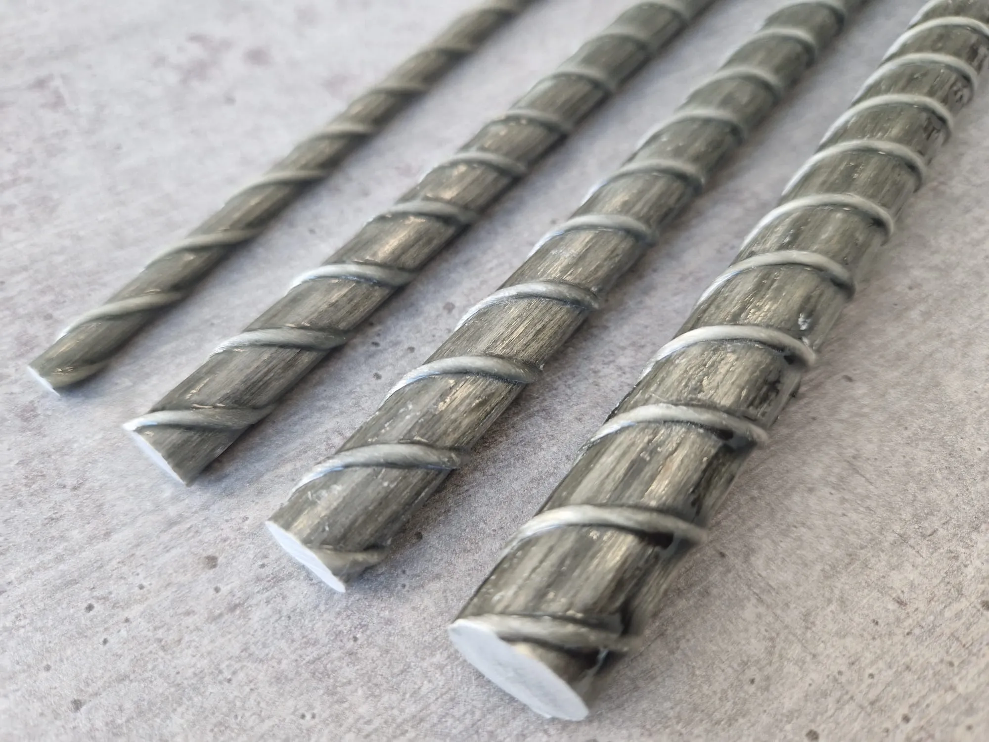
- Bond β
- ≈ 1.0 with sand-coated + helical-wrap GFRP per ETA 23/0523 (EAD 260023-00-0301).
- Code reference
- fib MC 2020 §17.5 + ACI 440.11-22. Swiss federal projects: pilot route via ETA.
What deck designers ask first.
- Yes — bridge deck slabs are one of the largest GFRP application categories in North America and an accelerating category in Europe. The design driver is chloride-induced corrosion of the top mat, which sees the heaviest exposure to de-icing salt and saline runoff. Standard practice is to specify GFRP for the top mat and retain steel for the bottom mat where ductility is required. This is what we call the hybrid design.
- A reinforced concrete deck slab where the top mat (the chloride-exposed face) is GFRP rebar, typically Ø 12 mm at 100–150 mm centres, and the bottom mat retains steel for ductility, fatigue resistance and seismic detailing. The hybrid design eliminates the chloride-driven corrosion path that ends most steel-only decks at year 20–30, while keeping the well-understood steel design for the compression zone. ACI 440.11-22 and fib MC 2020 §17 cover the design rules.
- A hybrid GFRP top mat typically doubles realistic service life — from a chloride-driven 20–30 year repair interval to 60+ years before structural intervention. Whole-life cost analysis (CAPEX + maintenance + closure-time opportunity cost) typically favours hybrid GFRP within the first 25 years of the deck’s life.
- For static and low-cycle loading — the regime of most highway bridge deck slabs — GFRP is well-characterized and approved under ETA 23/0523 (EAD 260023-00-0301). For high-cycle fatigue applications (railway bridges, heavy-cyclic industrial decks), the design rules in fib MC 2020 §17 apply reduced design stress to GFRP and we run a project-specific fatigue check.